
Has anyone got a drawing or exact specifications of the FRP Cambelt tool? Going to see if we can get some made up. Would anyone be interested in buying one if we did knock some up?
David
Racing Puma Owners Club
Board index ‹ FRP Q & A? ‹ FRP Cambelt Timing Tool
 Tue Mar 27, 2012 12:13 pm
Tue Mar 27, 2012 12:34 pm
Tue Mar 27, 2012 6:31 pm
Thu Mar 29, 2012 7:19 am
Thu Mar 29, 2012 12:47 pm
Wed Apr 11, 2012 2:16 pm
Fri May 04, 2012 9:35 pm
Fri May 04, 2012 10:16 pm
Awesome
Look forward to it
Tue May 08, 2012 12:34 am
Tue May 08, 2012 8:44 am
Tue May 08, 2012 9:23 am
Tue May 08, 2012 9:46 am
Tue May 08, 2012 10:28 am
Wed May 09, 2012 2:02 am
Wed May 09, 2012 9:46 am
Wed May 09, 2012 10:09 am
Wed May 09, 2012 10:18 am
Wed May 09, 2012 9:09 pm

FRP 241 - lsd equipped
Fri May 18, 2012 2:17 am
Thu May 24, 2012 8:56 pm
More to follow on this when I can find the time. Busy stripping the back end on mine for Polybushes, strut braces & powder coating. Then it's on to do similar to the front end. Also doing similar to my bike, (long overdue) which is a bit of a classic in it's own right, being a 'J' reg '91 Kawasaki Gpz900r A8 in fire cracker red. Time is at a premium at the mo.
FRP Cambelt Timing Tool
21 posts
• Page 1 of 2 • 1, 2
FRP314

Yes I would 
Matt
FRP #435
FRP #435

Have a look on PP http://www.pumapeople.com/forum/index.php?showtopic=101121quite detailed drawings and pictures.
change the "advertisement not permitted to puma people (without a gap in the word)
change the "advertisement not permitted to puma people (without a gap in the word)
Graham

HID headlights fitted ... I can now see where I'm going !
HID headlights fitted ... I can now see where I'm going !
Hi, Yes put me down for one.
May I suggest a couple of things. First have you thought about putting this question on other Club sites eg Puma People?
Also, may I suggest for NON DIY ers that there could be a problem using this no matter how accurately made.
Ford garages will not allow its' use, Independent garages may also not want to use it as if there is a problem with the work then
they can blame the free issue tool saying its out of spec etc. Just a thought. Good Luck and let me know progress if you go ahead.
Cheers John Arundel FRP426 and 476
The bar is only half the kit as far as locking the crank goes anyway... also, anyone who knows their onions when it comes to engines does not need the bar anyway... many prefer to use the older fasioned method up marking the flywheel... and turning the engine over when done just to check nothing has gone out of position.... When Harry did mine, he kind of did both as i had the bar, but it wasn't really needed...
Chris
Chris
I have given the matter of FRP cam belt replacement a fair amount of thought
In my mind the FRP timing issue comes down to one or two simple things.
1. The crank timing pulley is not keyed to the crankshaft, & is only retained in position by A.It's fit on the crank & B. The clamping of the crank stretch bolt.
2. The timing belt is enclosed at crank end by the lower belt cover.
3. The poly vee pulley/damper with it's stretch bolt must be removed to remove the lower belt cover.
4. Removing these two releases the crank pulley, leaving it susceptible to being shifted out of position relative to the crank & TDC. Dependant on the tightness of it's fit on the crank.
5. The crank pulley alignment with respect to the crank can no longer be relied on.
6. Re-timing this arrangement by marking the relative positions of the crank & cam pulleys is possible, but risky as it is wholly reliant on the crank pulley remaining in position.
7. Should the crank pulley have shifted slightly, (say by 1/4 of a tooth {1/8 cam belt pitch}), the timing would be out by a similar amount, yet would remain undetectable by the cam pulley/flywheel marking method.
8. For initial cam belt change, the most reliable course would be to use the correct tools (cam lock bar & crank lock pin).
9. Were it not for the lower belt cover, it may be that the belt could be replaced without risking shifting the crank pulley relative to the cam pulleys. In which case belt replacement would become a whole lot easier.
10. Whilst the purists among us would tend not to omit or modify something like this belt cover, as an engineer I would consider this for ease of maintenance on the basis that:- A. The FRP is most likely used in good weather (mine certainly is) & most unlikely to be used off road. Thus the chances of ingress of dirt etc is likely to be very low (this area of the engine is sandwiched between th block & the splash guard). B. There is no significant safety issue. & C. An FRP tends to get a cam belt change far sooner than the Ford recommended service interval of 80k miles or 5 years which ever is the soonest.
11. In the mean time I have recently acquired a genuine FRP cam locking tool & will try to produce an engineering drawing of the said item. Though I must say that will be easier said than done due to the relationship between the locating pin & the angled recess for the exhaust cam.
Subject item returned to home this evening, so it's out with mics, calipers & sharpest pencil. Drawing to follow.
coopersmotors wrote:
Subject item returned to home this evening, so it's out with mics, calipers & sharpest pencil. Drawing to follow.
Awesome
Look forward to it
FRP314
On subject, working drawings produced. Can somebody please tell me how to import the images into a post. I have 6 A4 pages or a .pdf file. HELP PLEASE!!
Last edited by coopersmotors on Wed May 16, 2012 1:59 am, edited 1 time in total.
You need to upload the pictures to a site like Photobucket http://photobucket.com/
Once you have signed up to the site and uploaded your pictures, you can link the pictures to the post.
Just copy and paste the command line which starts IMG into the topic.

Right click and look at the location of my picture and you will get the idea.
Once you have signed up to the site and uploaded your pictures, you can link the pictures to the post.
Just copy and paste the command line which starts IMG into the topic.
Right click and look at the location of my picture and you will get the idea.
Graham
HID headlights fitted ... I can now see where I'm going !
HID headlights fitted ... I can now see where I'm going !
Mine has a locating pin at the front is yours the original?
Cheers
bonnietiler
Cheers
bonnietiler
No a copy
Graham
HID headlights fitted ... I can now see where I'm going !
HID headlights fitted ... I can now see where I'm going !
None the worse for that as long as it works!
Bonnietiler
Bonnietiler
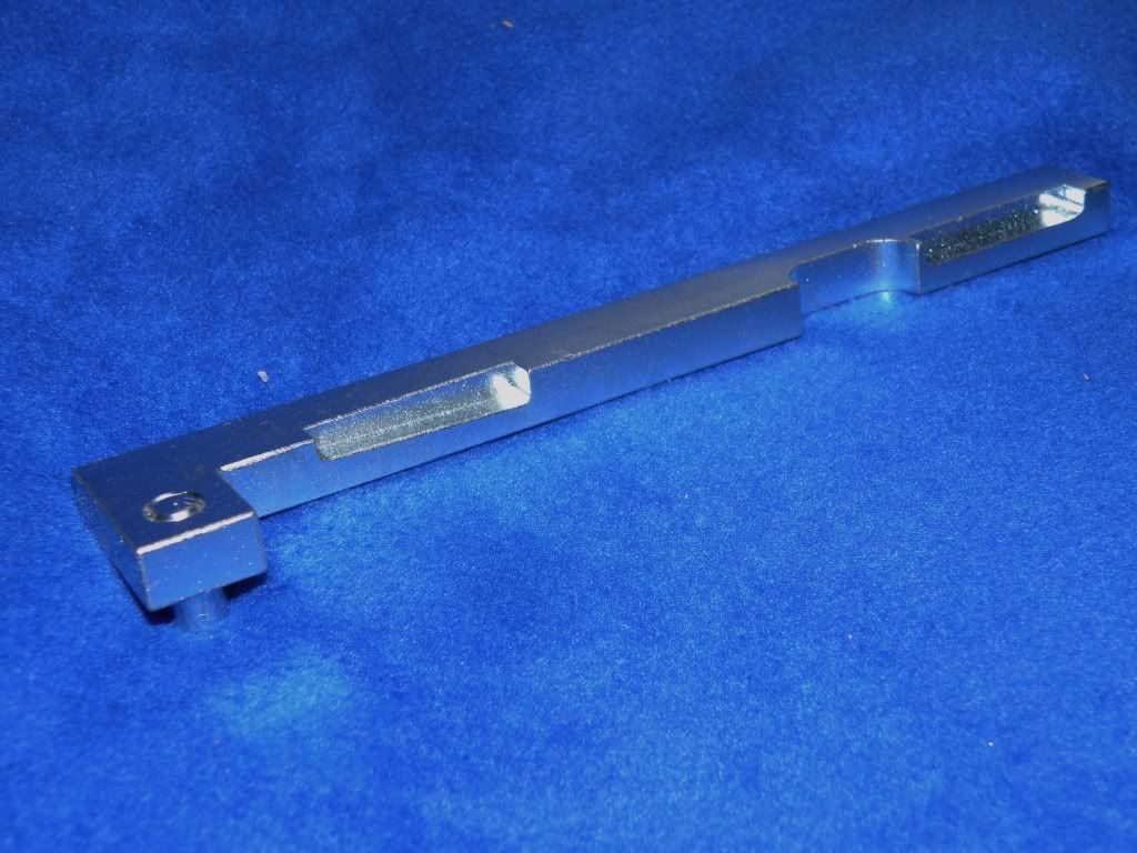
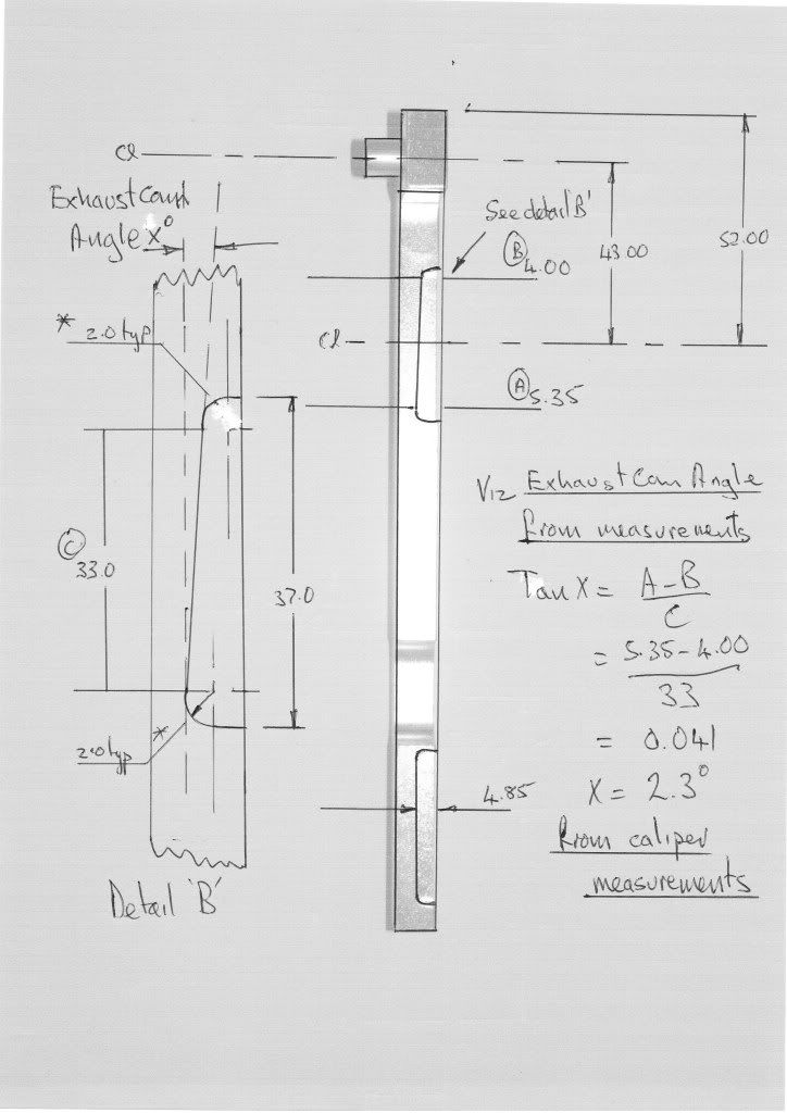
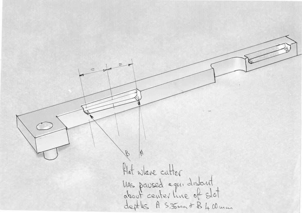
Thanks Dogsbody, hopefully this has worked ok as I havn't uploaded images to RPOC before. Photographed tool from all angles, printed in grey scale, outlined & added dimensions, scanned back in & uploaded. All measurements taken with digital caliper & depth gauge, as the tool is nominally metric I didn't use my mics (english) to avoid conversion problems. The critical part & the most difficult to measure accurately is the relationship between the dowel pin & the center line the angled cut out, which appears to be 43.00mm. The (2 degree) exhaust cam off set is milled through this point from a depth of 4.00mm to 5.35mm as near as i can determind. As I understand from my copy of Ford TIS the procedure for use of this tool is as follows:- 1. Holding the tool at 30/45 degrees to the exhaust cam, engage the dowel pin in the cambox dowel hole to the rear of the cam. 2. Whilst carefully adjusting the angle of the exhaust cam with a spanner on the cam hexagon, swing the tool around so that the angled flat starts to engage. 3. With this done shift attention to the inlet cam & do similar, adjusting until the tool seats fully home. 4. The tool should be quite a tight fit & may need tapping into place. -This to ensure that the exhaust cam is positively set at the correct angle. -I back calculated from the dimensions I took & came up With an angle of 2.3 degrees, which I didn't think was too bad really. IMPORTANT:- My concern with the tool pictured above, the copy without the dowel pin, is two fold. Firstly that part of the tool is possibley omitted due to the difficulty in manufacture (looks to me like a cnc mill generated taper). Secondly, & more importantly, without the dowel pin component of the cam locking tool, there is nothing to stop the bar being displaced to the rear, thus releasing the exhaust cam enabling it to shift position, because the seating of the cam is angled & not flat as in the standard 1.7 VCT engine (where a simple flat bar of the right thickness is sufficient).
To my knowledge crank lock pin & rest of the cambelt change procedure is as per std 1.7 VCT.
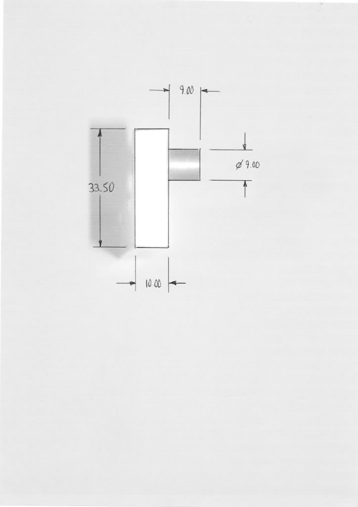
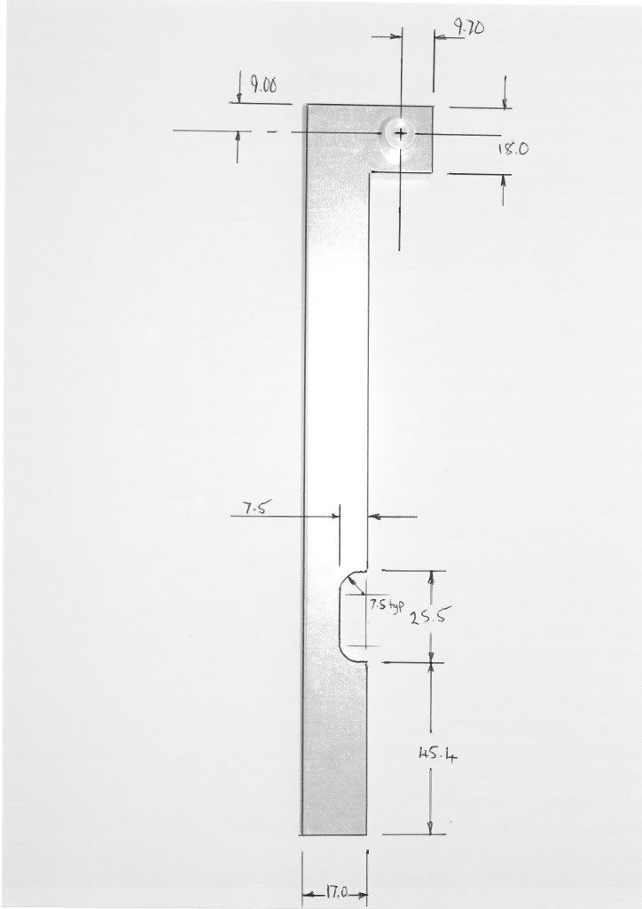
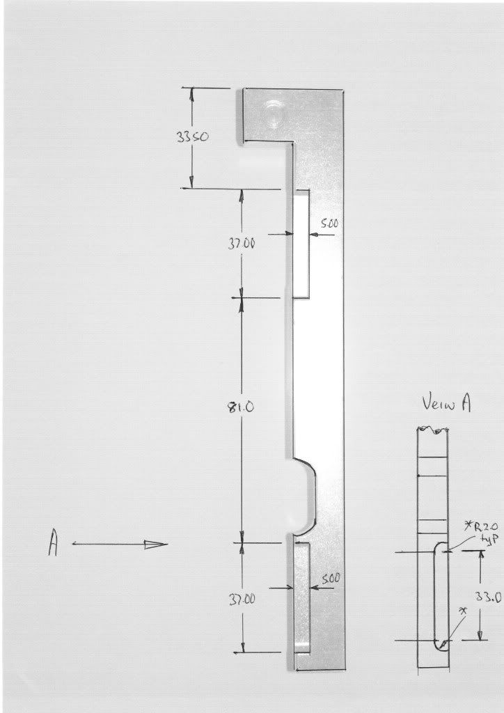
What follows are a series of working drawings/sketches taken as accurately as I could reasonabley manage:-
Failing that My Cam Locking Tool is available for weekly hire at any time for £25 a throw with a £100 returnable deposit to make sure it finds it's way home in one piece, All transactions through Paypal. Hope this is helpful to you all -Phil
To my knowledge crank lock pin & rest of the cambelt change procedure is as per std 1.7 VCT.
What follows are a series of working drawings/sketches taken as accurately as I could reasonabley manage:-
Failing that My Cam Locking Tool is available for weekly hire at any time for £25 a throw with a £100 returnable deposit to make sure it finds it's way home in one piece, All transactions through Paypal. Hope this is helpful to you all -Phil
I might add the lug tonight at work, won't take me long.
Just drill tap and counter drill a cap head to hold in place.
Bit of silver steel on the lathe to 9mm O/D
Just drill tap and counter drill a cap head to hold in place.
Bit of silver steel on the lathe to 9mm O/D
Graham
HID headlights fitted ... I can now see where I'm going !
HID headlights fitted ... I can now see where I'm going !
Cracking drawings mate...well done.. 
Ford engineer I know said "whats that bit for then" ?  The genuine Ford Puma cam locking tool doesn't have that bit.
The FRP ones does, just to make it more idiot proof he thinks.
He did a Puma cam belt on Saturday with their tool.
The FRP ones does, just to make it more idiot proof he thinks.
He did a Puma cam belt on Saturday with their tool.
Graham
HID headlights fitted ... I can now see where I'm going !
HID headlights fitted ... I can now see where I'm going !

Was the tool you used an original spx tool with the 6 digit number stamped into the side of it, greyish black in colour?.
FRP 241 - lsd equipped
No, but it sure beats Tippex
big boy al wrote:
Was the tool you used an original spx tool with the 6 digit number stamped into the side of it, greyish black in colour?.
More to follow on this when I can find the time. Busy stripping the back end on mine for Polybushes, strut braces & powder coating. Then it's on to do similar to the front end. Also doing similar to my bike, (long overdue) which is a bit of a classic in it's own right, being a 'J' reg '91 Kawasaki Gpz900r A8 in fire cracker red. Time is at a premium at the mo.
21 posts
• Page 1 of 2 • 1, 2